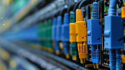
A network fiber optic cable carries data as pulses of light through extremely thin glass or plastic fibers. Unlike copper wiring, it does not send electrical signals along a metal conductor. This basic difference helps fiber support high bandwidth, long distances, and strong resistance to electromagnetic interference. The cable may look simple from the outside. Inside, its core, cladding, coating, strength members, and protective jacket work together.
The process begins with a transceiver, which converts electrical data into rapid light pulses. An LED or laser sends those pulses through the fiber core. The cladding keeps light inside by using a different refractive index. At the receiving end, another transceiver changes the light back into electrical data. The result is a digital signal that can travel between switches, servers, routers, and other network equipment. It happens quickly.
Real installations demand more than understanding light transmission. Technicians must select single-mode or multimode fiber for the required distance and equipment. They also inspect connectors, maintain clean end faces, and respect the cable’s bend radius. A tight bend can increase signal loss, even when the jacket appears undamaged. Optical power meters and visual fault locators provide useful evidence during testing. Small details matter.
Fiber is not automatically perfect. Poor splicing, mismatched connectors, or excessive dust can weaken performance. Installation practices also vary between buildings and network designs. This guide examines how network fiber optic cable works, where it fits, and what reliable deployment requires. The goal is practical clarity, not exaggerated promises.
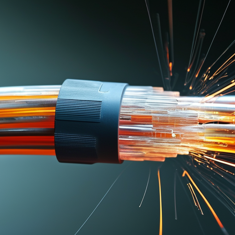
A network fiber optic cable is a communication cable that carries data through light. Its core usually contains very thin glass strands. A surrounding cladding keeps light inside the core. A protective jacket shields the fiber from moisture, bending, and surface damage.
In a network, an optical transceiver changes electrical data into rapid light pulses. The pulses travel through the fiber and reach another transceiver. That device changes them back into electrical signals for switches, servers, or routers. This process supports high bandwidth and long-distance communication with limited signal loss. Fiber also resists electromagnetic interference, which helps in factories and crowded equipment rooms.
Cable structure matters in real installations. Single-mode fiber commonly serves long distances, while multimode fiber suits shorter building connections. Technicians must check connector cleanliness, bend radius, polarity, and link power. A small scratch or dust particle can weaken the signal. The cable may look strong, but the glass inside remains delicate. That detail is easy to underestimate.
Testing should include visual inspection and optical measurements. A link can appear connected while still performing poorly. I have seen installation plans focus on speed and ignore future maintenance. That approach needs reconsideration. Clear labeling, proper slack storage, and documented test results make the network more dependable.
Network fiber optic cable carries data as pulses of light through extremely thin glass fibers. Its structure is simple in appearance, yet every layer has a specific job. TeleGeography’s 2024 Global Bandwidth Research reported that international bandwidth demand grew by about 29% in 2023. That pressure makes cable design increasingly important.
The core is the light-carrying center. It is usually made from high-purity glass, although some short-distance cables use plastic fiber. Around the core sits the cladding, which has a lower refractive index. This difference keeps light inside through total internal reflection. A primary coating protects the glass from moisture, scratches, and small bends. It feels soft. It is not the cable jacket.
Most outdoor cables add a buffer tube around one or more coated fibers. Loose-tube designs leave space for movement when temperature changes. Tight-buffer designs place protective material directly around each fiber, making indoor termination easier. Strength members, often aramid yarn or fiberglass rods, absorb pulling force during installation. The outer jacket then resists abrasion, water, sunlight, and chemicals. Some cables also include armor or a water-blocking layer.
Connectors are another practical component. Their end faces must stay clean and correctly aligned. A tiny speck can create noticeable insertion loss. IEC 60794 cable standards define performance and test requirements, but field conditions remain imperfect. Installers sometimes exceed bend limits while working quickly. That mistake can cause hidden attenuation. Cable selection should therefore consider fiber type, buffer design, pulling tension, bend radius, and the actual route—not only transmission speed.
Fiber optic cable transmits data as pulses of light through a glass or plastic fiber. The chart shows representative diameters of the main layers in a single-mode fiber cable; actual dimensions vary by cable design.
The core carries the light signal, while the cladding keeps the light inside the core through total internal reflection. The coating protects the glass fiber, the buffer and strength members provide mechanical protection, and the outer jacket protects the cable from moisture, abrasion, and environmental stress.
Network fiber optic cable carries data as pulses of light through extremely thin glass or plastic fibers. Each fiber has a central core and a surrounding cladding. The cladding reflects light inward, allowing the signal to travel long distances with limited leakage.
The transmitter changes digital data into rapid light pulses. A pulse can represent one value, while the absence of a pulse represents another. Inside the cable, the light repeatedly reflects along the core through a process called total internal reflection. Light moves.
At the receiving end, a photodiode detects these pulses and converts them back into electrical signals. Network equipment then interprets the signals as web pages, video, voice, or files. Single-mode fiber usually sends light through one narrow path, making it suitable for longer distances. Multimode fiber uses several paths and often serves shorter connections.
The process sounds simple, but real installations are less tidy. Bends, dirty connectors, poor splices, and damaged cable can weaken the signal. Small losses matter. Technicians measure optical power before trusting a new link, although measurements can still miss problems that appear only under heavy traffic. Fiber also does not carry electrical power, so connected equipment needs a separate power source. In a server room, this may mean checking both the glowing signal path and the silent equipment beside it.
Network fiber optic cable carries data as pulses of light through glass strands. It supports high speed, low latency, and long-distance transmission. The OECD Broadband Statistics update for December 2023 reported that fiber represented about 43% of fixed broadband connections across OECD countries. That growth makes cable selection more important.
Single-mode fiber uses a narrow core, usually around 9 micrometers wide. It supports long links, high bandwidth, and outdoor backbone networks. Multimode fiber has a larger core, commonly 50 micrometers. It suits shorter connections inside data centers and buildings. OM3 and OM4 cables support higher data rates than older OM1 designs. OM5 can carry several wavelengths, but its value depends on compatible equipment. OS2 generally serves long-distance single-mode links.
Cable construction also matters. Tight-buffered cable is practical for indoor patching and frequent handling. Loose-tube cable protects fibers from moisture and temperature changes. Simplex cables carry one fiber, while duplex cables use two fibers for sending and receiving data. In real installations, I often find the connector type causes more trouble than the fiber itself. The label is not always enough.
Tips: Check distance, transceiver wavelength, connector type, and bend limits before ordering. Use multimode for short indoor links when equipment supports it. Choose single-mode for future expansion. The wrong choice may still work, but poorly. Reflect on maintenance access, too; a technically perfect cable can become inconvenient in a crowded rack.
| Category | Fiber Type or Principle | Core / Cladding Size | Typical Light Source | Common Operating Wavelengths | Typical Transmission Distance | Typical Network Applications | Important Characteristics |
|---|---|---|---|---|---|---|---|
| How Fiber Works | Optical transmission through total internal reflection | Depends on the fiber construction | LED or semiconductor laser | Usually 850 nm, 1310 nm, or 1550 nm | From a few hundred meters to many kilometers | Data centers, campus networks, telecommunications, broadband access, and industrial networks | Electrical data is converted into light pulses, transmitted through the glass core, and converted back into electrical signals at the receiving end. |
| Single-Mode | One primary propagation mode | Approximately 9/125 micrometers | Laser diode | 1310 nm and 1550 nm | Typically several kilometers to tens of kilometers; the actual distance depends on the optical transceivers and link budget | Long-distance backbone links, metropolitan networks, telecommunications, and wide-area networks | Very low modal dispersion, high bandwidth potential, and long transmission distance. It generally requires more precise alignment than multimode fiber. |
| OS1 | Indoor single-mode fiber | Approximately 9/125 micrometers | Laser diode | 1310 nm and 1550 nm | Commonly used for links up to about 10 km, depending on the transmission equipment | Indoor backbone cabling, telecommunications rooms, and building distribution systems | Usually constructed with a tight-buffered design. It is suitable for controlled indoor environments and is generally less optimized for very long outdoor cable routes than OS2. |
| OS2 | Low-water-peak outdoor single-mode fiber | Approximately 9/125 micrometers | Laser diode | 1310 nm, 1383 nm, and 1550 nm | Commonly supports distances from several kilometers to tens of kilometers; the maximum depends on the optics and system design | Outdoor backbone networks, long-haul links, metropolitan networks, and telecommunications infrastructure | Lower attenuation and broader wavelength suitability than typical indoor single-mode constructions. It is often installed in loose-tube outdoor cables. |
| Multimode | Multiple propagation modes | Commonly 50/125 or 62.5/125 micrometers | LED or vertical-cavity surface-emitting laser | Usually 850 nm; some systems also use 1300 nm | Typically from a few meters to several hundred meters, depending on the multimode grade and data rate | Data centers, server rooms, enterprise buildings, and short campus links | Larger core size makes coupling easier and equipment can be economical, but modal dispersion limits distance compared with single-mode fiber. |
| OM1 | Multimode graded-index fiber | 62.5/125 micrometers | LED or multimode laser | 850 nm and 1300 nm | Approximately 33 m at 10 Gb/s under common standards-based conditions | Legacy building networks and older short-distance installations | Older multimode grade with lower bandwidth-distance performance than newer 50/125-micrometer grades. |
| OM2 | Multimode graded-index fiber | 50/125 micrometers | Multimode laser | 850 nm and 1300 nm | Approximately 82 m at 10 Gb/s under common standards-based conditions | Short building backbones and legacy data-center links | Higher modal bandwidth than OM1, but usually shorter 10 Gb/s reach than OM3 and OM4. |
| OM3 | Laser-optimized multimode fiber | 50/125 micrometers | Multimode laser | 850 nm | Approximately 300 m at 10 Gb/s under common standards-based conditions | Data centers, server rooms, and medium-distance high-speed links | Designed for efficient operation with 850 nm multimode laser systems and offers substantially greater bandwidth-distance performance than OM1 and OM2. |
| OM4 | Enhanced laser-optimized multimode fiber | 50/125 micrometers | Multimode laser | 850 nm | Approximately 400 m at 10 Gb/s under common standards-based conditions | High-density data centers, campus backbones, and higher-speed short-reach networks | Higher effective modal bandwidth than OM3, supporting longer distances at many parallel-optics data rates. |
| OM5 | Wideband multimode fiber | 50/125 micrometers | Multimode laser | Typically 850 nm to 953 nm for short-wavelength-division multiplexing systems | Often similar to or greater than OM4 for supported applications; the actual reach depends on the transceiver and wavelengths used | High-density data centers and applications using multiple wavelengths over multimode fiber | Optimized for a broader short-wavelength range and may reduce fiber counts in selected parallel or wavelength-multiplexed systems. |
| Simplex Cable | One optical fiber | Single-mode or multimode | Depends on the fiber system | Depends on the transceiver | Depends on fiber type and network equipment | Unidirectional links, sensing systems, and applications where one fiber is sufficient | Uses one fiber for transmission. Bidirectional communication requires wavelength separation or another system design. |
| Duplex Cable | Two optical fibers | Single-mode or multimode | Depends on the fiber system | Depends on the transceiver | Depends on fiber type and network equipment | Ethernet links, storage networks, building backbones, and most conventional two-fiber connections | One fiber normally carries transmit traffic and the other carries receive traffic, providing a straightforward full-duplex connection. |
| Tight-Buffered Cable | Fiber coating closely surrounds each fiber | Single-mode or multimode | Depends on the fiber type | Depends on the fiber type | Depends on the installed fiber grade | Indoor distribution, patch cords, riser cabling, and premises networks | Flexible and convenient for termination, but generally requires additional protection for harsh outdoor environments. |
| Loose-Tube Cable | Fibers are placed inside protective tubes, often with water-blocking materials | Usually single-mode, but other constructions are possible | Laser diode in most long-distance systems | Commonly 1310 nm and 1550 nm | Suitable for long outdoor routes when paired with appropriate optical equipment | Outdoor ducts, aerial installations, direct burial, and long-distance backbone networks | Provides better protection from moisture, temperature variation, and mechanical stress than typical indoor constructions. |
| Key Performance Factors | Attenuation, chromatic dispersion, modal dispersion, connector loss, and return loss | Determined by the fiber design and cable construction | Determined by the optical module | Must match the transceiver and fiber specifications | Calculated from attenuation, dispersion, transmit power, receiver sensitivity, and system margin | All fiber-optic network designs | Actual link performance cannot be determined from fiber type alone. Cable length, connectors, splices, bends, transceivers, and environmental conditions must also be considered. |
Network fiber optic cable is used wherever networks need speed, distance, and stable performance. It sends data as pulses of light through glass strands, instead of electrical signals through copper. In a modern office, fiber may connect the server room to switches, wireless access points, and security systems. A technician typically tests each strand with an optical power meter before activating the link. Small faults matter. A dirty connector can weaken the signal.
Fiber also forms the backbone of residential broadband. Passive optical networks carry one provider connection toward many homes through splitters. According to the International Telecommunication Union’s Facts and Figures 2023, about 5.4 billion people were online, representing 67% of the world’s population. That growing demand requires networks with higher capacity. Fiber supports this by using wavelength division, allowing multiple light channels to travel through one strand. The concept sounds simple. Field installation is not.
In data centers, fiber links connect switches across racks and buildings. They support cloud applications, video services, artificial intelligence workloads, and real-time collaboration. TeleGeography’s 2024 Global Bandwidth Research Service reports that submarine cables carry more than 99% of intercontinental Internet traffic. Those cables depend on optical transmission across thousands of kilometers. Fiber is not always the fastest solution in every room; short links can use copper for convenience and cost. Still, fiber usually offers better distance, lower interference, and greater upgrade potential. The weak point is often human handling, not the glass itself.