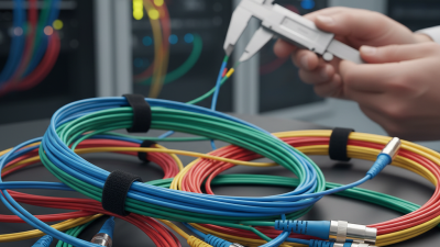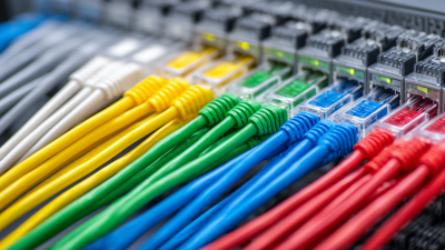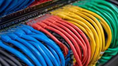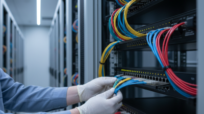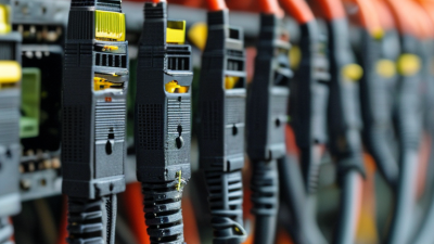
Choosing the right fiber patch cable begins with the link, not the product label. Check the equipment’s connector type, fiber mode, and required distance. A duplex LC cable may fit a switch neatly, while an older device may require SC connectors. The wrong interface will not connect, even if the cable looks right.
Jim Hayes, founder of the Fiber Optic Association, teaches a principle often summarized this way: “Inspect, clean, and verify every connection.” That advice matters in real installations. A fingerprint or dust speck on a connector can disrupt light transmission, though the cable itself is new. Match single-mode fiber to long-reach links and multimode fiber to compatible, shorter runs. Confirm the transceiver specifications, too; cable color alone is not a dependable guide.
Small details count. Measure the route, allow gentle slack, and avoid tight bends behind crowded racks. Select the needed length without pulling the cable taut across a cabinet. Check whether the link needs UPC or APC polish, and do not mate unlike polish types. It is easy to overfocus on speed ratings and miss connector compatibility. That happens. A fiber patch cable is a small component, but a poor match can cause link failures, extra troubleshooting, and wasted replacement parts. This guide will help you compare cable types, connectors, lengths, and installation needs before you buy. Verify the equipment documentation where specifications are unclear; assumptions are not a substitute for checking.
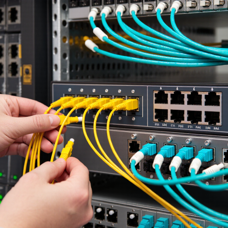
Before choosing a fiber patch cable, check the required data rate, link length, and transceiver specifications. A cable that fits the port may still exceed the optical reach or use the wrong fiber mode. For example, IEEE 802.3 specifies up to 300 meters for 10GBASE-SR over OM3 multimode fiber and 400 meters over OM4. For 100GBASE-SR4, the corresponding reaches are 70 and 100 meters. That matters.
Distance is only part of the decision. Singlemode links can cover longer spans, but the installed transceivers must support the same wavelength and fiber type. Check the connector and polarity, too. Duplex LC connections are common for many links, while parallel-optic equipment may require MPO connectors. A mismatch can leave a link dark even when the cable appears correct. Check the equipment documentation, not just the port shape.
IEEE 802.3-2022 provides these application-reach figures; actual performance also depends on channel loss and installation quality. Measure the route, including patch panels and service loops, rather than guessing from room dimensions. A few extra meters can matter near a link’s limit. I would also verify the existing fiber grade before ordering: cable labels can be hard to read, and assumptions are easy to make. The detail is less glamorous, but it prevents avoidable replacements.
Choosing fiber starts with the link, not the cable’s color. Single-mode fiber has a narrow core, commonly 9/125 µm, and supports long runs with compatible optics. It suits campus connections, building-to-building links, and routes where distance may grow. Multimode fiber, usually 50/125 µm, is often practical inside a data room or building. Shorter reach. Its optics can suit shorter links, but check the exact standard and speed.
Tips: Check both transceivers’ specifications before ordering. Match fiber type, wavelength, connector, and polarity. Measure the actual route, including service loops. A tidy 40-meter rack layout can become longer around trays and risers. Don’t choose by distance alone. Existing installed fiber may limit your options, which is easy to overlook.
For a new short link, multimode can be sensible when the optics support it and the route stays within their rated reach. For a longer or upgrade-sensitive route, single-mode often provides more headroom, though compatible transceivers affect cost. Verify optical budget and reach in the equipment datasheets.
Keep bends and pulling tension within cable specifications; tight turns behind a cabinet can add loss. “Future-proof” sounds simple, but it is not. A spare pathway may prove more useful than buying fiber for a hypothetical upgrade.
Start at the device ports, not the cable listing. An LC duplex lead has a compact 1.25 mm ferrule; SC uses a 2.5 mm ferrule. These interface dimensions are specified in the IEC 61754 connector-family standards. Check both ends: a switch and a transceiver may not use the same connector. A matching adapter can make the cable fit, but it cannot correct a mismatched optical interface. That is easy to miss.
Then match the end-face polish. UPC connectors have a flat physical-contact face; APC connectors use an angled face, commonly 8 degrees, to reduce back-reflection. IEC 61755-3-2 specifies angled physical-contact interfaces. Never mate APC and UPC directly. Their end faces can make contact poorly and increase loss. IEC 61300-3-35 defines inspection criteria for connector end faces, so inspect and clean both tips before installation. Do not rely on connector color alone; coding can vary. The awkward part: the right connector may still perform badly when dust is present. A visual check helps, but it is not a substitute for proper inspection.
The cable jacket should match the space it will occupy, not just the route shown on a drawing. Indoor runs may need a jacket rated for the building’s air-handling spaces; riser pathways can have different requirements. Check the project specification and local codes before ordering. Outdoor sections need protection from moisture, sunlight, and temperature swings. Moisture matters. A cable that looks sturdy on a workbench may still fail in a damp handhole.
Construction matters just as much. Tight-buffered cable is often practical for indoor routing and direct connector termination. Loose-tube designs can better protect fibers across outdoor runs, where temperature changes and water exposure are concerns. If the path passes near machinery or through a busy tray, armored construction may reduce the risk of crushing or rodent damage. It also adds weight and can make tight bends harder to manage.
Measure the actual route, including service loops, transitions, and bend points. Respect the cable’s minimum bend radius during pulling and after installation; sharp corners can cause loss even when the jacket appears untouched. A common planning mistake is choosing the toughest cable everywhere. That can add cost and complicate termination without solving the real hazard. Still, a clean drawing rarely captures every obstruction, so leave room to reassess the jacket and construction before the pull begins.
| Installation Environment | Recommended Jacket or Construction | Why It Fits | Selection Notes |
|---|---|---|---|
| General indoor equipment rooms and offices | PVC jacket; simplex or duplex cable | A practical choice for ordinary indoor patching where local fire-code requirements permit PVC. | Check the required flame rating and cable pathway rules. Choose simplex for one fiber and duplex for a two-fiber link. |
| Plenums and other air-handling spaces | Plenum-rated cable, such as cable marked OFNP where applicable | Designed and tested to meet specific flame and smoke requirements for plenum use in jurisdictions that recognize this classification. | Use the rating required by the applicable building code. Do not assume that an LSZH jacket is a substitute for a plenum rating. |
| Vertical risers between floors | Riser-rated cable, such as cable marked OFNR where applicable | Designed for vertical pathways and tested for flame propagation under the applicable riser classification. | Confirm local code requirements. A riser rating does not automatically qualify a cable for use in a plenum. |
| Public buildings or enclosed areas where low smoke and halogen-free materials are specified | LSZH (low-smoke zero-halogen) jacket | LSZH materials are designed to emit limited smoke and no halogen acid gases when exposed to fire, according to the relevant test standards. | Verify the exact LSZH standard and required fire classification. LSZH describes material behavior; it does not by itself establish plenum or riser suitability. |
| Outdoor runs exposed to sunlight or moisture | Outdoor-rated cable with a UV- and moisture-resistant jacket, commonly polyethylene (PE) | Outdoor cable designs are made to withstand environmental exposure better than typical indoor patch-cable jackets. | Check the product specification for UV, water-ingress, and temperature ratings. Use indoor/outdoor-rated cable if the route transitions into a building. |
| Areas where cables may be exposed to crushing, impact, or animal damage | Armored cable, with an appropriate indoor, outdoor, or indoor/outdoor jacket rating | Metallic or other protective armor adds mechanical protection compared with an unarmored cable. | Armor does not replace required fire ratings or pathway protection. Confirm grounding and bonding requirements for metallic armor, and check cable bend limits. |
| High-density racks and patch panels with limited routing space | Compact, flexible duplex or uniboot-style construction, if compatible with the equipment | Can reduce cable bulk and simplify routing where many patch cords are installed close together. | Check connector polarity, connector type, bend radius, and manufacturer handling instructions before ordering. |
| Routes with tight bends or frequent cable movement | Bend-insensitive fiber construction, such as OS2 fiber designed to meet ITU-T G.657 specifications | Some G.657 fiber types are designed to tolerate tighter bends with lower sensitivity to bend-related signal loss than conventional single-mode fiber. | Follow the cable’s stated minimum bend radius. Compatibility depends on the specific fiber type and link requirements. |
Before ordering: Match the cable’s fiber type, connector, polarity, length, and fire or environmental rating to the link and installation code. Always verify the cable datasheet and applicable local requirements.
Choosing a patch cable starts with matching the installed fiber and transceiver. Check fiber mode, connector type, polish, polarity, wavelength, and required reach. A duplex LC cable will not replace an MPO trunk without a compatible interface. Small details matter. The Fiber Optic Association’s reference guidance gives typical single-mode attenuation limits of about 0.4 dB/km at 1310 nm and 0.3 dB/km at 1550 nm. These figures describe fiber performance, not the total loss across a patch link, so check the transceiver’s link budget too.
Then verify the application’s speed and distance against the right fiber grade. IEEE 802.3 specifies up to 300 metres for 10GBASE-SR over OM3 and 400 metres over OM4. That difference can decide whether a cable run is suitable. Inspect the datasheet for insertion-loss limits, return-loss performance, bend radius, and test documentation. A low-loss label alone is not proof; request measured results for the cable assembly. The FOA also stresses end-face cleanliness, yet this check is easy to rush. Dust on a connector can undermine an otherwise compliant link. I would leave some margin for patch panels and future changes, rather than treating the maximum rated distance as a target.
Verify cable compatibility, performance, and quality specifications before installation.
These are standardized maximum link reaches for the specified 10 GbE optical interfaces: 10GBASE-SR uses OM3 or OM4 multimode fiber, while 10GBASE-LR uses OS2 single-mode fiber. Match the cable type, connector, polarity, and transceiver wavelength at both ends. Check the link budget and the cable’s insertion-loss and return-loss specifications; actual reach depends on the complete installed link.