
How to Choose Cat 6 UTP Cable for Your Needs?
Choosing the right cat 6 utp cable starts with the route it must serve, not just the price on the box. A cable running through a home office has different needs from one installed in a ceiling, workshop, or outdoor conduit. Cat 6 is rated for bandwidth up to 250 MHz and can support Gigabit Ethernet over standard channel lengths of up to 100 meters. Higher-speed 10 Gigabit Ethernet may work over shorter runs, but performance depends on installation conditions and interference.
Small details matter. Solid conductors suit fixed, permanent runs, while stranded cables are more flexible for patch leads. Check the jacket rating for the installation location, and confirm the cable is made with solid copper if dependable performance is important. Copper-clad aluminum can look similar, but it may not meet the needs of every network or Power over Ethernet setup. Read the product specifications carefully.
There is no perfect cable for every job. A low-cost choice may be fine for a short, simple connection, yet frustrating in a crowded cable tray or long wall run. Measure the route, allow a little slack, and consider nearby power cables, bends, and connector quality. Easy to overlook. This guide explains how to compare cable construction, length, ratings, and practical use so you can choose with clearer expectations—and know when the label alone is not enough.
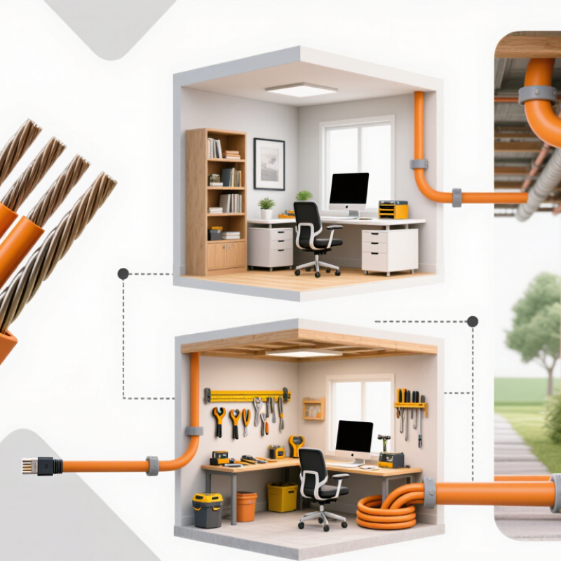
Define Network Needs: Cat 6 Carries 1 Gb/s to 100 m
Before choosing Cat 6 UTP, estimate how much data your network carries and how far each cable must run. For ordinary office work, video calls, and file access, Cat 6 can support 1 Gb/s over a channel length of up to 100 meters. That distance includes patch cords, not just the cable hidden in a wall. Measure the full route, including turns through ceilings and equipment racks. Leave a little slack at both ends. Measure twice.
A 100-meter rating is a limit, not a target. Long routes can become harder to manage when cables share crowded pathways or pass near electrical equipment. UTP has no foil or braided shield, so careful routing matters in areas with strong electrical interference. For most homes and small offices, however, it is a practical choice when installed properly. Check that connectors and patch leads are also Cat 6; one lower-rated part can restrict the link. It is easy to focus on the cable spool and overlook those short connections. That is an imperfect planning habit, but a common one. If devices need more than 1 Gb/s, confirm their ports and expected cable distance before buying.
| Selection Factor | What to Check | Practical Guidance |
|---|---|---|
| Network speed and distance | Required data rate and total channel length | Cat 6 supports 1 Gb/s Ethernet over a channel length of up to 100 m. A channel includes the fixed cable and connecting patch cords. |
| Higher-speed links | Whether 10 Gb/s is needed | Cat 6 may support 10GBASE-T over shorter distances, commonly up to 55 m under suitable installation conditions. For longer 10 Gb/s links, check the equipment and cabling requirements; Cat 6A is typically specified for 10 Gb/s up to 100 m. |
| Bandwidth rating | Category marking and rated frequency | Look for a clearly marked Category 6 cable rated to 250 MHz. Frequency rating is not the same as data rate; link performance also depends on installation and connected equipment. |
| UTP construction | Unshielded twisted-pair design | Cat 6 UTP has no overall foil or braided shield. Its twisted pairs help reduce interference, but careful routing away from strong electrical noise sources is still advisable. |
| Conductor material | Solid copper versus copper-clad aluminum | For permanent building cabling, choose conductors identified as solid bare copper. Avoid copper-clad aluminum for Ethernet cabling, as it does not provide the same electrical performance as copper. |
| Solid or stranded conductors | Where the cable will be installed | Solid conductors are generally used for fixed runs in walls or cable pathways. Stranded conductors are more flexible and commonly used for patch cords and frequently moved connections. |
| Indoor or outdoor environment | Jacket rating and exposure conditions | Use a cable jacket rated for its intended location. Outdoor runs need a jacket designed for outdoor exposure; direct-burial installations require a cable specifically rated for direct burial. |
| Building fire requirements | Local code and installation space | Select the applicable jacket rating for the installation location, such as riser or plenum where required. Requirements vary by building code and jurisdiction. |
| Run length and routing | Actual route, bends, and service loops | Measure the installed path rather than the straight-line distance. Keep the completed Ethernet channel within 100 m for a standard 1 Gb/s Cat 6 link, and avoid excessive pulling tension or tight bends. |
| Connectors and installation | Compatibility and termination quality | Use compatible Cat 6 components and follow the chosen wiring scheme consistently. Poor terminations, untwisted pairs, or damaged cable can reduce link performance. |
| PoE requirements | Power level, cable length, and installation conditions | Cat 6 can be used for Power over Ethernet when the cable and connected equipment meet the applicable requirements. For higher-power PoE or bundled runs, consider cable temperature rise and installation guidance. |
Related Posts
-
10 Best Cat 6 UTP Cables for Fast Reliable Networks
-
2026 Best UTP Cat 6 Cable for Global Buyers
-
Ultimate Guide to Choosing the Right Network Patch Cable for Your Home Setup
-

Understanding UTP Cable: Types, Uses, and Differences Explained
-

China Top Fiber Optic Patch Cord Manufacturers?
-
How to Choose the Best Cat 6a Cable for Your Network Needs?