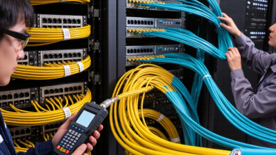
A fiber optic patch cord is a factory-terminated cable that connects optical equipment, panels, and outlets. It usually contains one or two glass fibers, protective jackets, and connectors such as LC, SC, or MPO. In a data center, it may link a switch to a patch panel across a short rack distance. The cable looks simple. Its performance is not.
Global connectivity makes this small component increasingly important. The International Telecommunication Union reported 5.4 billion people online in 2023, representing about 67% of the world’s population. Cisco’s Annual Internet Report projected global internet traffic would reach 5.3 zettabytes annually by 2023. These figures show why stable optical links matter inside dense networks. A poorly cleaned connector can add insertion loss. A sharply bent cable can weaken the signal. One careless bend may affect an entire connection.
Practical selection requires more than choosing a low price. Network engineers should verify fiber type, connector polish, polarity, insertion loss, return loss, jacket rating, and operating environment. TIA-568.3-D provides recognized guidance for optical-fiber cabling practices, while the IEC 61754 series defines connector interface dimensions. Quality reports from manufacturers should support those claims. Still, laboratory results do not guarantee field performance. Dust, repeated handling, and unclear labeling can create failures. That uncomfortable detail is often overlooked. A reliable fiber optic patch cord is therefore part of a complete system, not an isolated accessory. Understanding its construction and limits helps readers install, test, and maintain optical networks with greater confidence.
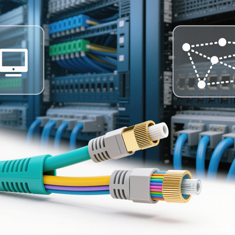
What Is a Fiber Optic Patch Cord?
A fiber optic patch cord is a factory-terminated cable that connects optical equipment, patch panels, and splice enclosures. Its core purpose is simple: carry light signals between two fixed connection points with minimal loss. In a rack, it may link a transceiver to a distribution panel. In a telecom room, it can connect separate fiber routes without permanent splicing.
This small cable supports large networks. The 2024 Global Bandwidth Research Service reported a 29% increase in international bandwidth use during 2023. That growth increases pressure on every connection point, including short patch cords. A clean connector matters. Dust on its end face can raise insertion loss, while a tight bend can weaken the signal. Technicians should check the connector type, fiber mode, polish style, and required bend radius before installation. A patch cord that fits physically may still be optically wrong. I have seen neat-looking links fail because polarity was reversed.
Tips: Inspect and clean both end faces before mating. Never touch the ferrule. Keep protective caps on unused ports. Route the cord in a gentle curve, not a sharp loop. Label both ends clearly. Test insertion loss and return loss after installation, preferably against the project’s accepted limits. The 2023 edition of ISO/IEC 11801 reinforces the need for structured cabling performance and channel testing. Still, field conditions vary. A perfect factory test cannot replace careful installation.
A fiber optic patch cord is a pre-terminated length of optical fiber used to connect network equipment, patch panels, and cross-connects. The chart shows representative maximum attenuation values commonly associated with standard multimode and single-mode fiber at key operating wavelengths. Lower attenuation indicates less optical signal loss per kilometer; connector insertion loss is additional and depends on the termination quality.
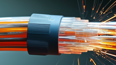
A fiber optic patch cord is a short, factory-terminated cable for connecting network equipment, panels, and optical modules. Its internal structure looks simple, but every layer protects signal quality. The central glass fiber carries light through a core and cladding. A polymer coating shields the glass from moisture and tiny surface damage. Around it, aramid yarn provides tensile strength, while the outer jacket resists abrasion, bending, and handling stress.
At each end, the connector contains several precise parts. The ceramic ferrule holds the fiber with micron-level alignment. The connector body keeps the ferrule stable and supports the coupling mechanism. A latch or threaded shell secures the connection. The boot protects the cable exit from sharp bends. It is a small part. It prevents large problems. IEC 61300-3-34 classifies connector insertion loss at approximately 0.50, 0.25, and 0.12 dB for different performance grades. These figures show why end-face geometry matters.
Real installations reveal the weak points. Dust on the ferrule can create reflection, attenuation, or permanent scratches. Excessive pulling can damage the fiber beneath an intact jacket. ITU-T G.657 guidance supports bend-tolerant fiber designs, yet “bend-resistant” never means bend-proof. Technicians should inspect, clean, and test both ends before connection. A visual check alone is insufficient. Optical loss testing remains more reliable, although testing practices are sometimes inconsistent. That deserves reflection.
A fiber optic patch cord is a factory-terminated cable for transmitting light between network devices. It usually contains one or two optical fibers, protective layers, and connectors at both ends. In field installations, I check the cord length before routing it through a rack. A few extra centimeters can prevent sharp bends and unnecessary tension.
Fiber type is the first practical classification. Single-mode fiber supports long-distance links and uses a small core for focused light transmission. Multimode fiber has a larger core and suits shorter connections, such as data center equipment. Mixing these types can cause severe signal loss. It may still look perfectly normal.
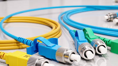
Connector design provides another clear distinction. Common forms include push-pull connectors, small duplex connectors, and threaded connectors for secure coupling. Connector end faces must remain clean and undamaged. Even a tiny dust particle can increase insertion loss. I have seen technicians replace an entire cord when careful cleaning would have solved the issue. That mistake is easy to make.
Cable design also affects selection. Simplex cords carry one fiber, while duplex cords carry two fibers for bidirectional communication. Tight-buffered cables are convenient for indoor patching. Armored versions offer stronger protection in exposed areas. Bend-insensitive designs tolerate tighter routing, but they are not impossible to damage.
Check the bend radius, jacket condition, connector polish, and polarity before installation. A visual inspection is useful, but test equipment remains more reliable.
What Is a Fiber Optic Patch Cord?
How Fiber Optic Patch Cords Transmit Data
A fiber optic patch cord is a short cable with optical connectors on both ends. It links equipment, patch panels, and network outlets. Inside, a glass or plastic fiber carries pulses of light. The fiber core guides light through internal reflection. The surrounding cladding keeps that light within the core.
Data transmission begins when network equipment converts electrical signals into light pulses. A transmitter sends these pulses through the fiber. At the receiving end, a detector changes the light back into electrical signals. Each pulse represents digital information, such as a web request or video frame. The process happens extremely quickly, often across long distances with low signal loss.
Single-mode fiber usually carries light farther through a narrow core. Multimode fiber supports shorter links and uses a wider core. Connector alignment matters because even a tiny gap can weaken the signal. Dust, scratches, and excessive bending also increase insertion loss or reflection. In real installations, technicians inspect and clean connectors before connection. They also respect the cable’s minimum bend radius.
One detail is easy to underestimate: a patch cord can look perfect and still perform poorly. Testing with an optical power meter provides stronger evidence than appearance alone. Specifications help, but actual measurements reveal installation problems. Careful handling remains necessary, even for a short cable.
| Data Dimension | Typical Data or Specification | How It Affects Data Transmission |
|---|---|---|
| Primary Function | Connects optical transceivers, patch panels, switches, and other fiber equipment | Provides a removable connection that carries data as pulses of light between network components |
| Transmission Medium | Glass optical fiber, usually with a 125 micrometer cladding diameter | Guides light through the fiber core using total internal reflection |
| Single-Mode Fiber | Approximately 9/125 micrometers; commonly used at 1310 nm or 1550 nm | Supports long-distance and high-bandwidth links with low modal dispersion |
| Multimode Fiber | Common core sizes include 50/125 micrometers and 62.5/125 micrometers; typically used near 850 nm | Allows multiple light paths and is commonly used for short-distance data-center and LAN connections |
| Common Multimode Grades | OM1, OM2, OM3, OM4, and OM5 | Higher grades generally provide greater effective modal bandwidth and longer supported distances for compatible equipment |
| Typical 10 Gb/s Multimode Reach | Approximately 33 m on OM1, 82 m on OM2, 300 m on OM3, and 400 m on OM4 | The actual link distance depends on the transceiver, fiber grade, wavelength, connectors, and total link loss |
| Typical Single-Mode Reach | Common Ethernet optical links support 10 km or more when paired with suitable long-distance transceivers | The fiber patch cord itself does not determine the complete link distance; the optical modules and link budget are decisive |
| Connector Configuration | Simplex uses one fiber; duplex uses two fibers for separate transmit and receive paths | Duplex patch cords support two-way communication over dedicated fibers and are common in Ethernet networks |
| Connector Interface | Common forms include LC, SC, and MPO-style multifiber connectors | The connector must match the equipment port, fiber count, polarity, and required optical performance |
| Polishing Type | UPC is commonly used for general digital links; APC uses an angled end face and is common where lower back reflection is required | The two mating connectors should use compatible polishing types to prevent poor coupling and excessive reflection |
| Insertion Loss | Typically about 0.2–0.5 dB per mated connection; the allowable maximum depends on the applicable standard and component specification | Higher insertion loss reduces the optical power reaching the receiver and shortens the available link margin |
| Operating Temperature | Many indoor patch cords are rated approximately from −20°C to +70°C, subject to the cable design | Operating outside the rated range can affect mechanical reliability and optical performance |
| Bend Sensitivity | Bend-insensitive fiber designs commonly support a minimum installation bend radius of about 10 times the cable diameter | Exceeding the bend limit may increase attenuation or permanently damage the fiber |
| Electromagnetic Immunity | Fiber carries light rather than electrical current | It is not affected by electromagnetic interference and does not create an electrical ground loop |
| Data Transmission Process | An optical transmitter converts electrical data into modulated light; the receiver converts the light back into electrical data | The patch cord provides the low-loss optical path between the transmitting and receiving equipment |
| Typical Patch Cord Length | Common lengths range from approximately 0.5 m to 30 m; longer assemblies may be available for specific installations | Longer cords add a small amount of fiber attenuation and should be included in the link-loss calculation |
| Key Installation Requirements | Correct fiber type, connector type, polarity, end-face cleanliness, bend radius, and optical budget | Correct selection and handling help maintain signal strength, network speed, and link stability |
Note: Performance values are typical reference ranges. Actual results depend on the fiber standard, transceiver specifications, connector quality, installation method, and total optical link budget.
Selection, Installation, and Maintenance Considerations
Fiber optic patch cords connect optical equipment, panels, and network outlets. Their selection affects signal stability, troubleshooting time, and upgrade flexibility. The OECD Broadband Data report for December 2023 recorded fiber at approximately 42.6% of fixed broadband subscriptions across member economies. That growth increases the need for disciplined cabling practices.
Choose single-mode OS2 for long-distance links and multimode OM4 for shorter data-center connections. Match the connector type, polish, fiber count, and transmission requirements. Check insertion loss and return loss against the equipment specification. A patch cord that fits physically may still perform poorly. I have seen installations fail because polarity was ignored. Small errors become expensive later.
During installation, keep protective caps on unused ends. Clean connectors with lint-free tools, then inspect them before mating. IEC 61300-3-35 provides widely used guidance for end-face inspection. Respect the stated bend radius, avoid sharp tray edges, and label both ends clearly. The FOA reference materials commonly emphasize inspection, cleaning, and testing as routine controls, not emergency repairs.
Tips:
Keep spare cords sealed and separated by type. Never touch the ferrule. Test after every relocation. Record loss measurements, connector polarity, and inspection dates. Maintenance logs often reveal recurring damage patterns, although teams sometimes record too little. A simple photo of the rack can prevent confusion during nighttime repairs.